Concepts
- Feature - A part surface
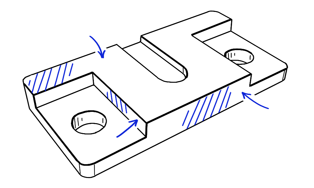
- Feature of size (FOS) - A cylindrical or spherical surface or a set of two
opposed elements or parallel surfaces associated with a size dimension.
- Internal FOS - Internal surfaces such as a hole or slot.
- External FOS - External surfaces such as a shaft or tab.
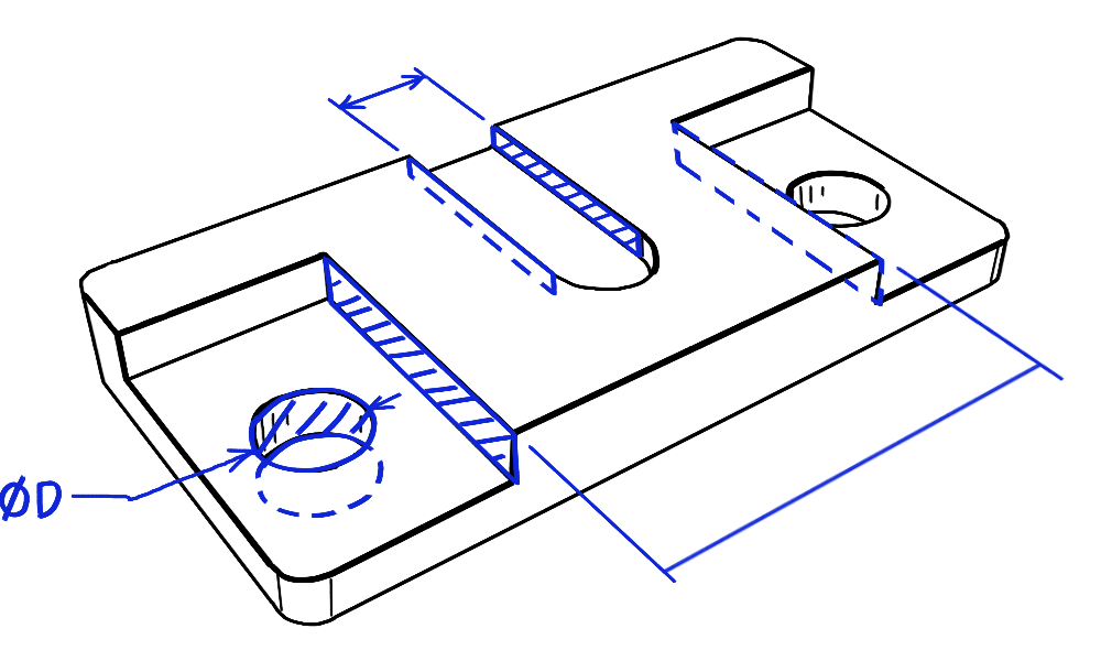
- Feature of size dimension - A dimension associated with a FOS.
- Non-feature of size dimension - A dimension not associated with a FOS.
- Actual Local Size - The value of any individual distance at any cross section of a FOS (for example any two point measurement taken with a pair of calipers).
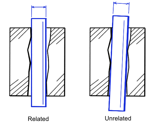
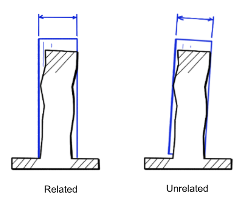
- Envelope, Actual Mating (AME) - A similar perfect counterpart - for an external feature
of size is the smallest size that can be contracted about the feature; for an
internal feature of size is the largest size that can be expanded within the
feature - so that it just contacts the surfaces at the highest points. This
surface resides outside the material.
- Related AME - is constrained in orientation to the applicable datums
- Unrelated AME - is not constrained in orientation to the applicable datums and is rotated to align the the axis of the part
- Envelope, Actual Mininum Material - a similar perfect counterpart of largest size that can be expanded in a external FOS, and the smallest size that can be contracted about an internal FOS. Can also be related and unrelated. This surface resides inside the material.
- Basic dimension - A dimension that represents the theoretically exact size, true profile, orientation, or location of a feature or gage information such as datum targets. When basic dimensions are used, they must be accompanied by geometric tolerances. Typically denoted by enclosing the value in a rectangle.
Material Conditions
Valid for features of size (FOS). Every feature of size has a maximum and minimum material condition.
Maximum Material Condition (MMC)
The condition in which the geometry contains the maximum amount of material within the stated limits of size. Examples:
- Smallest hole
- Largest shaft
- Narrowest slot
- Largest tab
Minimum Material Condition (LMC)
The condition in which the geometry contains the minimum amount of material within the stated limits of size. Examples:
- Largest hole
- Smallest shaft
- Largest slot
- Smallest tab
Regardless of Feature Size (RFS)
Indicates geometric tolerances apply at any increment of size of the feature within its size tolerance. In other words, the geometric tolerance is valid at whatever size the part is produced at.
No symbol is associated with this condition as it is the default condition.
Modifiers
| Term | Abbreviation | Symbol |
|---|---|---|
| Maximum material condition | MMC |  |
| Least material condition | LMC |  |
| Projected tolerance zone | - |  |
| Tangent plane | - |  |
| Diameter | - |  |
| Radius | - |  |
| Controlled radius | - |  |
| Reference | - | ( ) |
Feature Control Frame
Geometric tolerances specified on a drawing use a feature control frame for their syntax. This consists of a rectangular box divided into three main subdivisions:
- geometric characteristic symbol
- tolerance value + any modifiers
- datums

Rule #1
Where only a tolerance of size is specified, the limits of size of an individual feature prescribe the extent to which variations in its form and its size are allowed.
This is often paraphrased as "perfect form at MMC". At MMC, no further deviation in form is allowed. When the size departs from MMC, some form error is allowed. (Perfect form means all applicable form controls: straightness, flatness, circularity, and cylindricity.)
Can be overridden when a straightness control is applied to a FOS or if a note explicitly stating such is included.
Rule #1 does not affect the location, orientation, or relationship between features of size.
Does not apply to parts that are flexible or to stock parts (e.g. bar stock, tubing, etc.).
Inspection may be performed with a Go gage for FOS at MMC and a No-Go gage for FOS at LMC.
Rule #2
RFS applies, with respect to the individual tolerance, datum reference, or both, where no modifying symbol is specified. MMC or LMC must be specified on the drawing where required.
Where a geometric tolerance is applied on an RFS basis, the tolerance is limited to the specified value regardless of the actual size of the feature.