Fusion 360 has good support for parameters in CAD documents and the ability to drive designs using them. Here we will create a fully parametric design based on functional design parameters, using the following table as an example. As you can see, nominal dimensions can be specified to create different versions of the design:
Setup
To input parameters open the Parameters dialog which is available under the Modify panel of the Design tab. Here we will enter all of the pertinent values governing our design. Putting as much information here at the outset can make the design more robust and parametric.

Layout Sketches
Layout sketches are then made and dimensions linked to parameters. For the table we will create a rectangle for the overall shape and an offset plane equal to the height. Set the two dimensions for the rectangle equal to the width and height variables. This is accomplished by simply typing their names in the dimension field text. Fusion 360 gives you some suggestions after you start typing to which you can hit Enter to autocomplete.


These two items are sufficient for creating the table top, as seen below, simply by adjusting the Start property of the Extrude feature. Next, we add a sketch for one of the legs. We can add a coincident constraint to the first sketch to keep the leg at the extents of the table, which is applied at each of the lower left corners of the leg and table rectangles. Since we defined a leg dimension for the structural HSS, we link the width and thickness dimensions to the parameters (indicated by the addition of "fx").

Create Components
Legs
Now it is time to start creating components. All of the features created thus far exist at the top level. To add a new component right click on the top of the tree and click "New Component". This adds a "Component1" and activates it. We will create a Leg so we rename it "Leg". By showing only the leg sketch we add a new extrude and extrude the leg profile. Since we will be performing a component pattern later, we add addional features to the component in the feet and casters. This way anything we do here will be copied to the other three legs.

To add a baseplate we create a new sketch on the component origin plane and by only showing the layout leg sketch we created initially we can make sure to constrain to that and not anything else. It is generally a good practice to constrain and create references to upstream sketch geometry rather than to solid features since solid features are more likely to change, and thus result in broken references which must be repaired.

Next we extrude this profile, add some fillets to the HSS extrusion, and add 4 holes in the base plate.

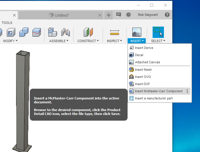
Finally, we add a McMaster-Carr part using the built-in importing feature. We do this while still in the Leg component since it will be included in the rectangular pattern that we are about to do and makes some sense to think of it as part of the leg assembly. However, it could also be added in at the top level since that probably more realisticly reflects its location in the BOM.
After doing that and adding a caster, bolt, and nut, we have a leg assembly ready to be patterned:

We then activate the top level and create a Component Pattern. Select Components as the type and click on the Leg. Click on the global X axis to set the pattern direction and in the distance we can enter in one of our parameters, or an expression using parameters. Our values will be: width - leg_width for the x value and depth - leg_width for the z value, and adding a negative for the z-direction.

Cross Members
Next we add cross members. The procedure is the same as for the legs, making sure to hide created bodies in order to create relations to existing sketch geometry and not solid geometry.

We extrude, add fillets, and pattern components to add additional members.


Side Plates
To create side plates we first add a plane at the front face of the table. This can be set by either keying in an offset equal to depth/2 or by offsetting to a sketch point. Then, we sketch in some geometry for the plate, and make sure to dimension it in a way that allows it to be scaled in the x-direction without error. Additional expressions could be added here, for example to set the length of the horizontal side lines to be some fraction of the overall width.

Top
Lastly, the top plate is added. Here we simply re-use the layout sketches created initially. In the extrude dialog box, set the Start property to From Object and select the construction plane. Then, add a Push/Pull (offset face) feature to extend the sides over the legs, if desired.

Conclusion
To complete the design I add Ground features to each component to prevent components from moving. Apply any physical properties through the Physical Materials context menu and at this point the design should be complete. Scaling and resizing of the table is easy and can be accomplished by changing values in the Parameters dialog box.
The key points to this approach are:
- Create parameters specifying all relevant and pertinent properties for your design
- Create as much reference geometry in the top level as needed: sketches, planes, axes
- Create components for parts
- Make sketches at the component level reference top-level sketches and reference geometry
- Make sketch and feature dimensions incorporate parameters or parameter expressions
- Add Grounds to components at the end of the timeline